Feeder Type Design
Enter the feeder type design
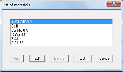
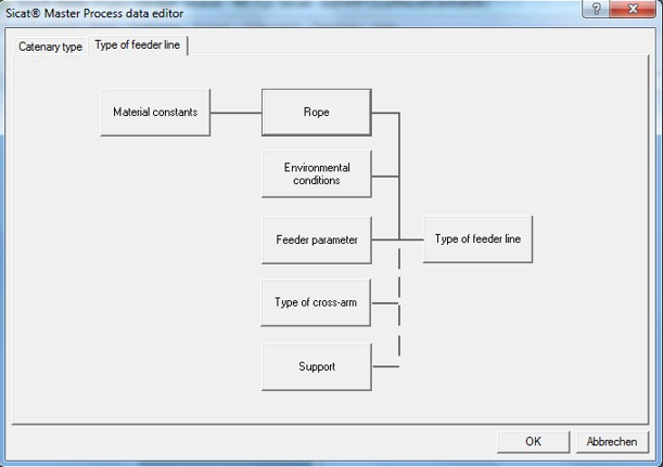
In this paragraph it is explained, how and where you can do all necessary entries to create a feeder type design. The register Type of feeder line is the main page for the definition of process data for feeders. After clicking on one of the buttons a list dialogue appears which enables the Creation, Editing, Deleting, and Output of the data from the list.
The feeder line type was defined as an independent type of the catenary. For this reason it is also independent from the catenary design type. You can define feeder lines, parallel, return and by-pass-feeders independent from the catenary.
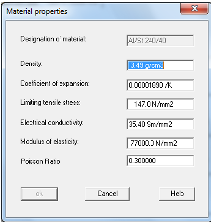
First you have to define the feeder material (Material constants for all contact wires and ropes).
Definition of the surrounding conditions
For the definition of the process data for the feeder type design there have to be some predefinitions. These are the type of rope with the according rope material, environmental conditions, information regarding the feeder parameters, types of cross-arms and support points.
The last three data provide specification values for new feeders in the catenary layout module and can be newly defined at any time, just like contact wire and system height.
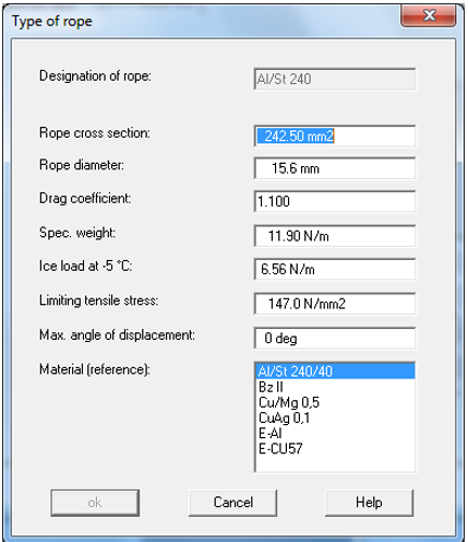
The inputs for the rope parameters, their material constants and the environmental conditions correspond to those of the wire type in the catenary type definition in the prior chapters.

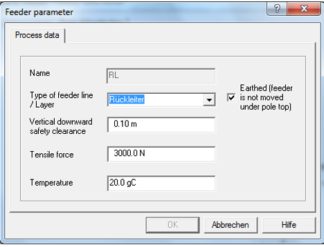
A name has to be entered by the creation of a new feeder parameter in the tab Process data of the Feeder parameter dialogue. This cannot be changed later because the name field is disabled for further editing.
You can determine the feeder type over a combo box. The selection points are defined in the data Sicat.ini and they can be adjusted and expanded by the system administrator. With every entry of this combo box a reference to an output layer and therefore the notation (colour, line type) in the location plan is connected. The number for the Layer intended for feeders is limited to 15. Definitions of several feeder types that are displayed on the same layer are possible.
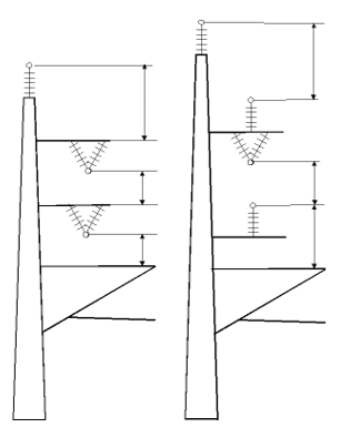
For the calculation of a pole length a vertical safety clearance has to be given to the bottom of the feeder. Vertical safety clearances of the feeder are defined as distance between feeder height and the highest point in the underlying feeder or cantilever. If there are support isolators fixed on the underlying cross arm, the feeder height will be decisive in this cross arm. If the feeder in the underlying cross arm is fixed with V- Suspensions, the cross-arm height will be decisive for the vertical safety clearance. If a cantilever is located under the feeder, the bigger value of the height of the messenger wire or the height of the upper cantilever fastener will be decisive. Examples for the definition of the safety clearance are shown in the next figure.
The modus for the calculation of the vertical distance of the feeder can be modified in the section [CalcMode] in the file Sicat.ini over the system variable bCalcModeVertBELAbstLeiterLeiter. If the variable is set on 1 all safety clearances refer to the vertical distance feeder-feeder. The two following values, tensile force and temperature, show the state of the feeder force, for example by the erection. Hence the sag for each field can be calculated according to the temperature from the environmental conditions.
Please fill the fields and confirm your entry with OK.
Enter the Types of cross-arm the feeder type design
In the dialogue window Type of cross arm a name has to be entered. This cannot be changed later because the name field is disabled for further editing.
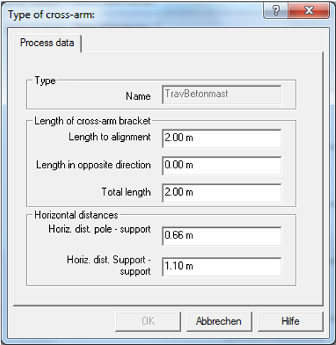
The length of cross-arm bracket can be defined in the upper part of the dialogue. Each cross- arm has an alignment (away from track, to path, in direction of track according km-x, in direction of opposite track according Km-0) in the catenary design module. Asymmetrical cross- arms can also be created by specification of the length in the alignment and the length in opposite direction.
The lower part of the dialogue box allows the input of the horizontal distance for the supports that are fastened on the cross-arm. The distances pole first support and support support have to be entered. If a new feeder is created with a cross-arm in the catenary design module the length are set according to the default of the feeder line type. The same applies for the duplication of feeders on cross-arms.
Enter the support points for the feeder type design
When a new support point is created in the dialogue Feeder line support, a name has to be given for that. This cannot be changed later because the name field is disabled for further editing.
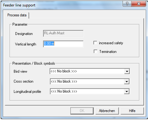
The height difference between feeder and fixing at support is given in the field vertical length. For standing insulators his is a positive value. For suspension insulators, V-type suspension etc a negative value has to be entered.
Increased safety and catenary termination can be defined with the two check boxes. If a feeder line support on the pole has increased safety, this will be written in the pole list. Feeder line supports that are marked as catenary termination split a feeder line in sections. The State parameters Temperature and tensile force can then be declared for each feeder section (between two catenary terminations) in the feeder dialogue of the catenary layout.
The graphical view in the location plan and cross section is given in the combo boxes for the block symbols. In the bird view the symbol only acts a part by the termination. The blocks have to be included in the file Blocksio.dxf (see section Administration) and have to be entered in the block-section of the file Sicat.ini.
Create a new feeder type design
Assign those to the catenary and denominated the catenary.

Change an existing catenary type
Start the project manager, get the project which has to be changed, and call the desired state of progress and the suitable object.